Brushless Speed Controllers, An Inside Look
By Lucien Miller, President, Innov8tive Designs
Brushless Electronic Speed Controllers are probably the most misunderstood and overlooked component in an R/C Electric Power System. These little marvels of modern electronics handle huge amounts of power and current, while switching power on and off at a rate of thousands of times per second, all to make a brushless motor spin a prop to power our model aircraft. In this informational article we will look at the basic function of Brushless Speed Controllers, talk about some of the features they have, and dispel some of the myths and misinformation surrounding them.
While Brushless Motors are relatively simple devices, consisting of a stator wrapped with 3 phases of enamel coated wire, a rotor assembly with a shaft and several magnets glued to it, and a set of bearings to make everything spin freely, Brushless ESC’s are relatively complicated devices with a Microprocessor, current sensors, temperature sensors, switching voltage regulators, dozens of discrete capacitors and resistors, driver transistors and an array of high current FET output transistors.
Speed controllers come in a wide variety of sizes with various amp capacities, voltage ratings and styles of BEC (Battery Eliminator Circuits). There are also specialized versions of ESC’s that are designed to work with Aircraft, Multirotors, Cars, Boats, Helicopters, and other applications.
Helicopter ESC’s will have special features such as Soft-Start, Governor Modes, and Auto-Rotation Bailout Delay, specific to the needs of helicopters. They also typically have large aluminum heat-sink cases to dissipate the heat from the ESC when they are mounted inside an enclosed canopy.
Multirotor ESC’s typically use specialized firmware that allows them to receive control data directly from a flight controller board, at a much faster rate than other types of speed controllers can process. Some specialized ESC’s for smaller racing quads have 4 separate ESC’s all combined on a single PC board to keep the controller compact and centralized in the frame of the quad.
Boat Speed controllers will often have liquid-cooled heatsinks that are attached to the FET transistors, with inlet and outlet tubes, so water can be pumped through the ESC in the radio box, where it normally receives no cooling air. Water is fed into the heatsink from a pickup tube at the back of the boat and ejected overboard after it runs through the heatsink to pull the heat away from the speed controller.
Car controllers will often require Hall-Effect position sensor feedback from car motors that are built with these position sensors inside. This allows for smooth application of power when the throttle is first opened up, and exact phase position control over the entire range of operation of the throttle.
In this article, we will focus on Airplane speed controllers, which have a feature set designed for aircraft, and rely on air cooling within the fuselage of an aircraft. There are many different types of airplane ESC’s available today. Some have Switching Type BEC circuits, some have Linear Type BEC circuits and others have no BEC circuit inside and are typically referred to as OPTO type ESC’s.
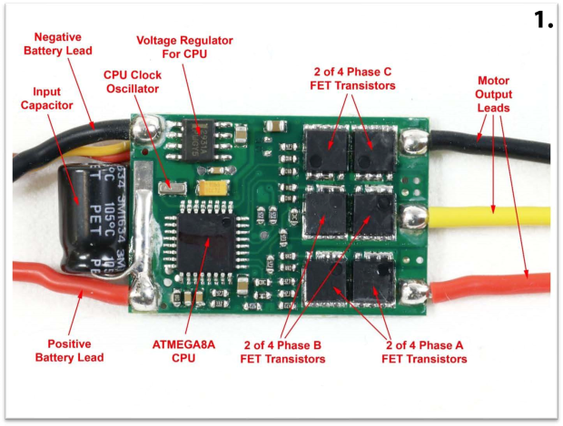
Below are a few photos that enable us to “Look under the Hood” of a couple different kinds of speed controllers to be able to see all the different components that it takes to make one work. In the first photo is the front side of a Cobra 22-Amp ESC, which has a 2-Amp Linear type BEC circuit.
1. In this photo, on the left side we can see the battery input leads that bring power into the ESC from the flight battery. Right at the input of the ESC, in between the battery leads, you will typically find one of more input filter capacitors. The purpose of these capacitors is to store a charge of voltage to provide smooth DC power to the ESC as it switches from one phase to another to make the motor spin.
Next is the CPU, which stores and runs the program that makes the ESC work. Above the CPU is the Clock Oscillator that sets the precise timing the CPU needs to function properly. CPU’s also require a very precise stable voltage source, typically 5 volts, so a high precision voltage regular is used to provide this dedicated power to the CPU.
In order to switch the power from the battery to the coils of wire in the motor, an array of 3 sets of high-power FET Transistors is used, one set for each phase. Because the small FET transistors used in RC speed controllers can only handle a few amps of current each, they are grouped together in rows to get higher current capacity. In the ESC shown above, there are 4 FET’s per phase, with each carrying 5.5 amps of current so there is a total of 22 amps of current capacity available.
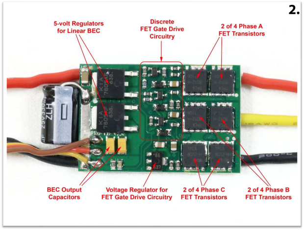
2. This next photo shows the opposite side of the same Cobra 22-Amp ESC.
This ESC has a Linear type BEC circuit that uses a pair of 5-volt regulator IC’s, each rated for 1 amp of current, so the total output of the BEC circuit is 2 amps at 5 volts. This ESC uses a series of discrete resistors, diodes and capacitors to make up the FET Gate Drive Circuitry. The purpose of these components is to boost the signal coming from the CPU to be able to turn on the FET transistors quickly and efficiently. There is also an additional voltage regulator to provide power to the Gate Drive circuitry as well as the remaining 2 FET transistors for each phase of the motor outputs on this side of the ESC circuit board.
As you can see, there is quite a bit of circuitry there underneath the heat-shrink wrap on your average speed controller! The fact that you can get all of those parts working together on a PC board, and have it sell for only $20.99 is actually quite remarkable!
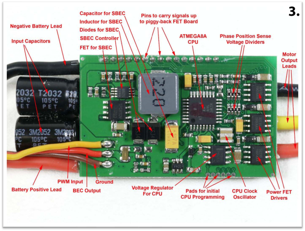
Now let’s take a look at the inside of a larger Cobra 80-Amp speed controller. This ESC is rated for use on up to 6 LiPo cells, and because of that, it uses a Switching Type BEC circuit that can handle higher battery voltage. This ESC also uses two PC boards, piggy-backed on top of one another, with a row of connecting pins on one side to carry the signals from one board to the other. In this design, CPU, Switching BEC and all of the FET gate drive components are on the main board, and all the FET power transistors are on the piggy-back board.
3. This photo shows the main board, which contains the CPU, BEC and FET gate drive electronics.
Most of the components on this ESC are the same as those on the smaller 22-Amp model that we already looked at earlier. There are 2 main differences on this one. First, instead of using voltage regulator IC’s to make up the BEC circuit, this one uses a switching type BEC. There are 5 main components in a switching BEC: The controller chip that does all the high-speed switching, a small FET transistor to turn the main battery power on and off, Diodes to keep the current flowing in the proper direction, an Inductor to store charge and a Capacitor to store and filter the BEC output voltage. We will get into the differences and operation of Linear versus Switching type BEC circuits a little later in this article.
The other main difference in this ESC is the use of 3 dedicated FET Gate Driver chips instead of a bunch of individual discrete parts. This is done to reduce the space needed and to provide a stronger signal to drive the FET’s, because this ESC uses a group of eight 10-amp FETS per phase, for a total of 24 FET’s.
The same CPU and Voltage regulator that was used in the 22-Amp ESC is used here in the 80-Amp model. Once again, we also have a pair of input leads coming from the battery and a set of 3 output leads going to the motor.
In between the input leads, instead of a single 330uF capacitor, there is a pair of 470uF capacitors. Since this ESC runs higher currents through it, we need more capacitance at the input to filter out the voltage fluctuations.
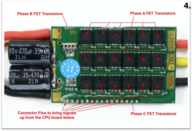
4. This photo shows the other side of the 80-Amp ESC, where all the FET Transistors are located.
Here we can see 6 FET transistors per phase. There are 2 more transistors on the back side of this board in each phase for a total of 8. As a side note, there are solder pads for a total of 4 transistors per phase on the back side of the piggy-backboard. On the 80-amp ESC two of these slots are occupied with transistors for a total of 8 FET’s per phase, and on the 100-Amp model, all four slots are filled for a total of 10 FET’s per phase.
On both of these speed controllers, there is an aluminum heat-sink plate attached to the FET’s to help pull the heat out of them during use. These are typically held in place with a silicone pad that has adhesive on both sides. To finish the ESC a sleeve of heat shrink tubing is placed over the assembly and shrunk down tight.
Now that we have looked at the inside of the speed controller and have a basic understanding of all the parts that make up a speed controller, we can talk about the operation of them and discuss some of the common misunderstandings that people have about them.
Our Brushless Speed Controllers essentially work by converting the DC power from a battery into 3-phase AC power to run the motor. In most brushless motors that are used in model aircraft, there are just 3 wires that go from the ESC to the motor. Since there are no sensors in the motor to provide position information, this leads to the question, “How does the ESC know when to change the power output from one phase to the next to keep the motor rotating, and how do you vary the speed of the motor in the process”?
To answer this question, we need to look at how the ESC functions to send power out to the motor.
Contrary to what some people believe, the ESC does not vary the voltage to the motor. When the FET transistors turn on, all they can do is either send the full voltage from the battery to one motor lead or connect one of the motor leads to ground. In a speed controller, the FET transistors are arranged in a configuration known as a 3-Phase H-Bridge.
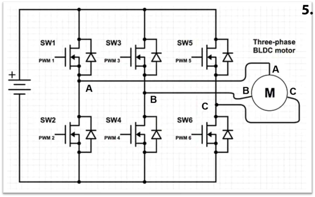
5. A simplified example of this is shown in this schematic diagram.
In this diagram, a battery is shown to the left, the FET transistors are shown in the middle, and motor is shown to the right. In the first power cycle, transistors 1 and 4 are turned on. This applies the voltage from the battery to the A terminal of the motor and the B terminal is connected to the battery ground. This will energize the coils in the motor connected to the A and B terminals and cause the motor to rotate a small amount.
During this time, terminal C is not connected to the battery voltage or ground, it just sits there, but while it is sitting there, something magical happens! As the motor rotates from the power being applied to terminal A and B, one of the magnets inside the motor passes directly over one of the coils in phase C of the motor. When this happens the changing magnetic field in that coil causes a voltage spike to be generated which is sent back to the CPU inside the ESC. When the CPU sees this voltage spike, it knows that the motor has rotated far enough, and now it is time to change which transistors are turned on to continue rotating the motor.
Next, the CPU shuts off transistors 1 and 4 and then turns on transistors 3 and 6. This connects terminal B of the motor to the battery voltage and terminal C to the battery ground. Once again, the motor starts to rotate, and the CPU looks for a voltage spike to be generated on the disconnected phase A of the motor. Once the motor rotates a little more, and the CPU sees the voltage spike from the phase A lead it knows that it is time to switch again.
To complete the 3-phase cycle, the CPU turns off transistors 3 and 6 and turns on transistors 5 and 2. This connects The C terminal of the motor to the battery voltage and terminal A to the battery ground. Just like before, the motor continues to rotate while the CPU watches for the voltage spike to be generated on the now disconnected phase B of the motor. Once that happens, the entire process starts all over and repeats over and over again to continue making the motor spin around.
During each cycle of going through three phases, a brushless motor will rotate past 2 magnets in the rotor can. Most of the brushless outrunner type motors made today for model aircraft use what is commonly known as a DLRK configuration that uses a stator with 12 slots and 14 magnets glued to the inner surface of the rotor can. Since the motor rotates 2 magnets per each complete 3-phase cycle, these motors need to go through 7 complete 3-phase cycles to make the motor go around 1 revolution.
The only problem with this process is that the voltage spike generated by the unpowered phase is only strong enough to be seen by the CPU if the motor is already spinning at several hundred RPM. If that is the case, it creates an interesting question, “How does a brushless ESC start up a motor from a dead stop”?
There are actually 2 different sections of code in the firmware that runs in a brushless speed controller, these can be looked at as the Start-up Section and the Run Section of the code. When you first power up a speed controller, you must have the throttle stick in the idle position, or else the ESC will not arm itself. When you open the throttle, the ESC first uses the Start-up section of the program. During this Start-up phase, the ESC sends out a pre-set series of pulses, in the proper sequence, for about ½ of a second to get the motor “kick-started” and spinning in the proper direction. Once the motor is spinning at a fast enough speed, the ESC switches to the Run Section of the code and starts listening for the power spikes to come in from the unpowered phase in order to get the timing needed to know when to switch from one phase to the next. If you close the throttle for more than second or so while the plane is in the air, the ESC will revert back to the Start-up Section of the program in preparation for the throttle to be opened back up and the process repeats.
Now that we have the motor started and running, this brings up yet another question. How do you vary the speed of the motor if all the transistors can do is supply the full battery voltage to the motor when they turn on? This is where the PWM effect or Pulse Width Modulation comes into play. When you apply power to a motor, if you are able to switch the power on and off very quickly, at a rate of thousands of times per second, The motor sees the average power that is delivered. For example, if the power is turned on and off such that it is on half the time and off half the time, the motor sees the average power delivered and runs at 50% throttle. If the power is on ¼ of the time and off ¾ of the time, then the motor sees that as 25% power.
A term used frequently with speed controllers is the PWM frequency. This is the rate at which the transistors are turned on and off to vary the average power to the motor during each power cycle. Most speed controllers use a frequency of 8 Kilohertz or 8 KHz, which turns the transistors on and off at a rate of 8,000 times per second. Some speed controllers use other PWM frequencies such as 12 KHz, 16 KHz or 32 KHz, depending on the application and how fast the motor is spinning.
When a motor is running at 100% throttle, with no load applied, it will spin at a speed equal to the Kv value of the motor multiplied by the battery voltage. For example, if you have a motor that has a Kv value of 1000 RPM/Volt and you power it from a 3-cell LiPo battery that puts out 11.1 volts, at full throttle this motor will spin at a speed of 1000 x 11.1 or 11,100 RPM. If you reduce the throttle, the PWM effect starts to kick in and the total average power to the motor decreases and the motor slows down.
To help visualize this, there are a series of screenshots from an oscilloscope that follow, showing the voltage being applied to a motor at different throttle levels.
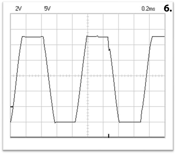
First, we will look at an oscilloscope screenshot of the voltage waveform of a motor running at 100% throttle.
6. In this diagram, each box up and down is equal to 2 volts, and each box right to left equals 0.2 milliseconds of time. Counting the boxes up and down, from the bottom section of the waveform to the top it is just a tiny bit more than 5-1/2 boxes, and with 2 volts per box, this equals a bit over 11 volts. It is actually 11.1 volts, which is the voltage of the 3-cell LiPo battery that was used during this test.
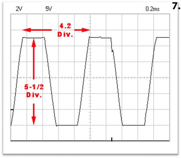
If you look at a point on first rising edge of the waveform to the same point where the second rising edge, you will see that distance is equal to 4.2 boxes or 4.2 divisions on the screen.
7. With each of these boxes equal to 0.2 milliseconds, the time duration from the beginning of one pulse to the next is 4.2 x 0.2 or 0.84 milliseconds. To convert this time into a frequency you take 1 and divide it by 0.84 milliseconds and you get 1190 Hertz. This means that from the time that one phase gets a power pulse, until the time that the same phase gets another power pulse is happening 1190 times per second. The math may be getting a little complicated for some readers, but if we take this 1 step further, earlier we said that it takes 7 complete cycles to make the motor go around 1 revolution, so if you take 1190 and divide that by 7 you can get the speed that the motor is rotating, which in this case is 170 revolutions per second. To convert this into the more common Revolutions Per Minute or RPM, we multiply 170 times 60 to get a motor speed of 10,204 RPM.
The motor that was being used in this test had a Kv value of 920 RPM/Volt. If we take 920 and multiply that by the battery voltage of 11.1 volts, we get an expected no-load RPM of 10,212 RPM. So, the numbers we read from the oscilloscope trace above almost exactly match the expected RPM of the motor!
Next, we can look at what happens when we reduce the throttle from 100% down to a lower throttle level such as 80% throttle.
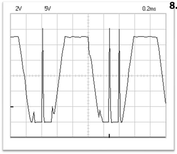
8. In the next oscilloscope screenshot, we can see the waveform going to each of the motor phases while it is running at 80% throttle.
Now the PWM effect is starting to kick in, and the power is being turned on and off several times per power pulse. If you look at the second part of the waveform in the above diagram, you can see how the voltage get pulled to ground about 80% of the time, and then goes back up to the battery voltage about 20% of the time. The average power of this pulse is 80% of what the power was in the last diagram, and this makes the motor slow down a bit. Now, if you look from the beginning of one wave to the beginning of the next one, the distance has increases from 4.2 squares to 4.5 squares, and doing the math on that, the RPM has dropped from 10,204 RPM to 9,524 RPM.
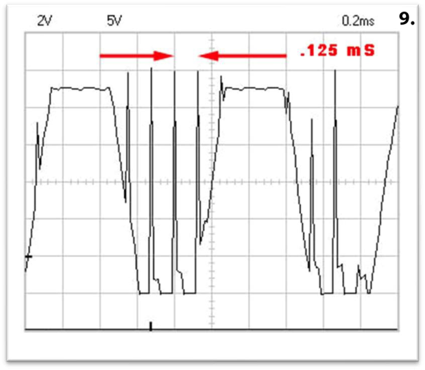
9. Next, if we take this a step further, and reduce the throttle level down to 60% throttle, the voltage waveform to each of the motor phases looks like what is shown in the next screenshot.
Now if you look at the bottom side of the first part of the above waveform, you can see that it is being pulled to ground about 60% of the time and goes back up to the battery voltage 40% of the time. This reduces the total power going to the motor to 60% of what was received at 100% throttle, and once again the motor slows down. Now from the beginning of one pulse to the beginning of the next pulse is 5 squares, and doing the math again on that gives a motor speed of 8,570 RPM. The motor being tested in these screenshots was running without a prop on it, so the RPM drop is much less than what you would get if there was a prop on the motor.
Another important thing can be seen in this screenshot. If you look at the time from one voltage pulse to the next, it is a hair over 0.6 boxes and is equal to 0.125 milliseconds. To convert this time into a frequency, we once again divide 1 by 0.125 mS and we get 8000 Hz or 8 KHz. Where have we seen that number before? That is the PWM frequency that the speed controller is working at! For those of you that have always wondered what the PWM frequency was, now you know! During each power pulse that goes to the motor, whenever you are running at a power level less than 100% throttle, the PWM effect kicks in and chops each power pulse into several smaller power pulses at a rate of 8000 times per second, AND each of those pulses is powered on for whatever percentage the throttle level is, and it is off for the rest of the time.
At 60% throttle each power pulse is on 60% of the time and off 40% of the time. At 30% throttle, each smaller pulse is on 30% of the time and off 70% of the time and so on. When a brushless motor is running at around 10,000 RPM, the power is being switched on and off to each phase of the motor at a rate of 1000 times per second, and each of those pulses is further broken up into smaller parts at a rate of 8000 times per second. If your ESC runs a PWM frequency of 12 KHz, then each power pulse in broken up at a rate of 12,000 times per second, and if you are running a PWM frequency of 16 KHz, then each pulse gets broken up 16,000 times per second! When you stop and think about it, there is a LOT of stuff going on inside the little speed controllers that we often take for granted!
So now we know what is inside a speed controller, how they start and run a motor, and how the PWM effect kicks in to vary the power, and therefore varies the speed of a brushless motor. However, there are a lot of other things that go on inside an ESC that we can also look at.
BEC Circuits
BEC’s or Battery Eliminator Circuits are a feature that most speed controllers have in them. For decades, in traditional glow engine powered models, a 4-cell Ni-Cad or Ni-MH rechargeable battery was used to provide 5 volts to power the radio receiver and servos during a flight. These batteries were typically sized so that they would have enough energy to last for 4 or 5 normal flights.
When models started being powered with electric power systems, there was not much sense in carrying a second battery in the plane, in addition to the motor battery, to power the receiver and servos. However, since the motor batteries are typically 12 volts, 16 volts or more, you have to step that higher voltage down to a lower value in the 5-to-6-volt range to power the receiver and servos. This is where the BEC circuit comes in.
The smaller early ESC’s that only ran on 2 or 3 LiPo cells, typically 8 to 12 volts, were built with what is known as a Linear BEC circuit. These BEC’s are nothing more than a 5-volt regulator IC, such as an LM7805, that takes the higher input voltage, drops it down to 5 volts at the output, and then converts the remaining excess voltage into heat that gets dissipated into the heatsink tab on the part and then into the PC board of the speed controller.
The problem with these BEC circuits is that although they are quite simple, they are horribly inefficient, and throw away more energy than they use. They also only produce the full rated current when they are run from a 2-cell battery. Because of the amount of heat energy they give off, if you run them on a 3-cell battery, you have to limit or de-rate the servo current to about ½ of the rated value of the BEC to keep the voltage regulators from getting too hot. If you try to run an ESC with a Linear BEC on 4 cells, you have to limit the current output to 1/4th of the rated value, which is barely enough power to run 1 servo, or else the voltage regulator IC’s will get so hot they will go into over-temperature protection and shut themselves off. For these cases, you must “Disable” the BEC circuit by disconnecting the red wire in the control lead to keep the BEC voltage from exiting the ESC.
Almost all ESC’s that are designed to run on 4 or more LiPo cells have what is known as a Switching BEC. In a switching BEC, you have a small FET transistor that switches on and off about 150,000 times per second taking small pulses of the full battery voltage and running them through a filter circuit that contains a diode, capacitor and inductor. This filter circuit smooths out all the voltage pulses and provides a steady voltage output.
For example, if you are running a 4-cell LiPo battery that is putting out 15 volts, the Switching BEC circuit will turn on 1/3 of the time and off 2/3 of the time during each cycle, and feed this signal into the filter circuit. The filter will average out these pulses and put out a steady 5 volts to send to the servos and receiver.
Because Switching BEC circuits only take as much power as they need to make the lower voltage required, very little power is wasted and converted to heat. Where Linear type BEC circuits typically have a low efficiency of between 40 to 60%, Switching type BEC circuits typically have a very high efficiency of 91 to 93%, so very little heat is created.
Switching BEC circuits also self-adjust to different input voltages and can run at much higher voltages. If you run the same BEC on 6 cells instead of 4 cells and have 22 volts instead of 15, instead of switching on 1/3 of the time and off 2/3 of the time each cycle, it will only have to turn on a little less than 1/4th the time and be off a little over ¾ the time to make the same 5 volts at the output.
Switching BEC’s also often have an adjustable output voltage which is selectable by the user.
When Linear BEC chips are made, they are set to a fixed voltage and cannot be changed. With Switching type BEC circuits, you can usually move a jumper, or change a value in the ESC program and adjust to output of the BEC to 5.0, 6.0, 7.4 or 8.4 volts as needed for the specific servos you are using. Switching BEC’s also normally have much higher current available for the servos, so you can run larger, more powerful servos or more servos as needed for your aircraft.
Motor Brake
Virtually all speed controllers have a Brake setting of some kind or another. Some ESC’s have a simple brake with an On or Off option, while other ESC’s will offer multiple brake levels with 3 or 4 different settings. In all of these options, when an ESC “Puts on the brakes”, what is does is send a continuous low level of power to one phase only, and holds it there without switching. When you do this, the energized poles in the stator act as a constant electromagnet and the nearest magnets in the rotor, that are of the opposite polarity, line themselves up with the energized poles and just stay locked in that position. By varying the power level sent out to the motor you can get a Soft, Medium or Hard brake level.
The brake action is useful for planes such as motor-gliders that have folding props. On these, you want the prop to come to a complete stop when the throttle is shut off, so the oncoming air pushes against the prop blades and folds them back against the aircraft fuselage. Another use for the brake is if you are flying a plane with no landing gear that you have to belly slide in for landings. You can apply the brake and lock the prop in a horizontal position, so a blade does not strike the ground during landings.
Low Voltage Cutoff
Another common feature that is built into most speed controllers is Low Voltage Cutoff or LVC. This feature monitors the voltage of a battery, and if the voltage gets too low, it will either completely shut off power to the motor (often called Hard Cutoff) or it will not allow the motor to go above 50% throttle (often called Soft Cutoff).
LiPo batteries do not like being discharged below a certain level. Ideally, you should not use up more than 80% of the battery capacity during a flight, leaving 20% of the battery capacity in the pack at the end of a flight. If you discharge a LiPo battery past 90% it will start to do permanent damage to a pack. The LVC acts as a safeguard to let you know when you have hit a critical level of power usage, and by either shutting off power completely or reducing power to a maximum of 50% throttle, it gives the pilot a clue that it is time to land, right now!
Many ESC’s will give you different levels of LVC, allowing you to choose the voltage per cell where LVC will kick in such as 3.2, 3.3, 3.4 or 3.5 volts per cell. Others will simply give you options such as Low, Medium, and High to choose from. If you do use LVC, it is best to use the Soft Cutoff option in most cases. The worst thing that can happen is to do a pass across the field, go to full throttle and pull up into a steep climb, and then have LVC kick in and kill the motor. This usually results in a stall with the plane crashing into the ground. If the power simply drops to half throttle when LVC kicks in, you still have enough power to nose over, go around the field 1 time and land.
Motor Timing
In addition to these features, speed controllers will also usually have the option to vary the Timing of the motor. For many pilots this is a confusing option which can cause some misunderstanding. Most ESC’s offer multiple timing options that are user selectable with a programming card. The most basic option is AUTO timing. In this mode, the ESC looks at the timing pulses coming back from the motor and adjusts itself automatically to give smooth reliable operation over the full range of throttle. Most ESC’s have this setting as the default condition, and in 95% of the applications, this works fine.
Some ESC’s will offer multiple options such as Low, Medium and High timing, while other will offer timing levels in specific angles such as 6 degrees, 12 degrees, 18 degrees 24 degrees and so on. The timing on brushless motors is virtually the same thing as spark plug timing on gas engines. In gas engines, in order to get complete burning of the fuel-air mixture in the cylinder you have to fire the spark plugs a certain number of degrees BEFORE the piston reaches the top of the stroke. This gives time for the burning to take place and for the pressure to fully build up so it can do the most work against the piston.
With electric motors, a similar thing takes place. When the CPU sends out a signal to apply power to one of the motor phase coils that signal first goes to the FET gate driver, then to the FET transistor. After the transistor turns on, it takes a finite amount of time for the current to flow into the stator coil and for the magnetic field to fully form in that coil. If you wait until the magnet is lined up exactly over the top of a stator coil before you apply power to that stator coil, by the time the magnetic field builds up in the coil to its full level, the motor will have already rotated several degrees, and possibly completely past the magnet, depending on how fast it is rotating.
To get the most power out of the motor, the CPU will send out the signal to turn on power to a stator coil a set number of degrees before the magnet lines up with the stator pole to give time for the magnetic field to fully build up and provide the most power to the magnet. The optimum timing for a brushless motor varies from one application to the next, depending on several factors including the rotational speed of the motor, the load on the motor, the number of magnets in the rotor assembly and speed controller being used.
Having the timing set too low will simply cause the motor to put out less power. However, setting the timing too high can have serious negative impacts and possibly even damage your motor. In a gas engine, if you set the spark plug timing to far advanced the engine and develop spark knock and even backfire. A similar thing can happen in an electric motor if the timing is too far advanced. You can get the timing so far advanced that instead of being attracted to the next magnet forward in the rotor can, the magnet in the opposite direction is actually closer and the motor tries to stop in its tracks and reverse direction. Obviously, this cannot happen due to the momentum of the rotating mass of the rotor assembly, but it can send shock waves through the rotor can and this can weaken and damage the glue joints on the magnets causing them to work loose.
When you have the timing set too far advanced, the motor will misfire during acceleration and it will sound as if you are throwing small stones into the prop as the motor runs. If you ever experience this after advancing the timing on an ESC, stop running the motor immediately and go back to a lower timing setting.
Motor Acceleration Time or Delay
Some ESC’s will allow you to change the rate at which the motor accelerates when the throttle is immediately moved from idle to full throttle. This feature can help keep the ESC from losing sync with the motor during rapid acceleration, especially if you are using a larger, heavy prop. Whenever you rapidly open the throttle from idle to full throttle, it takes a certain amount of time for the prop to spin up to the desired speed. Small lighter props can accelerate very quickly and go from a dead stop to 20,000 RPM in about ½ of a second. On the other hand, a very large heavy prop may take 2 seconds or more to spin up to full RPM.
Since our sensorless brushless ESC’s require feedback from the motor to know when to switch to the next phase, if the ESC is ramping up the speed of the pulses faster than the prop can accelerate and keep up with the ESC, then the motor can fall out of sync with the ESC. When this happens, the motor emits a loud screeching sound, much like fingernails on a chalkboard, and then the motor comes to a halt. When the motor falls out of sync with the ESC, the rapidly changing electromagnetic forces, which normally cause the motor to spin by pushing and pulling the magnets in the direction of rotation, instead make the rotor can vibrate like a speaker and emit the noise that you hear. When this happens, the only way you can get the motor to start again is to reduce the throttle to idle, wait a second and then slowly open up the throttle again to get the motor turning. To prevent this from happening, the ESC can often be set to slowly increase the speed of the motor over a pre-set period of
time, regardless of how fast you open up the throttle on the transmitter. The normal default setting for the Motor Acceleration Time is typically around 0.3 to 0.5 seconds, depending on the ESC brand. Some brands of ESC’s will have distinct time value options for the motor acceleration such as 0.3, 0.5, 0.7, 1.0 and 1.5 seconds while others will have names for the options such as Fast, Normal and Slow or something similar. If you do have a large heavy prop on your motor, and you experience a screeching noise from the motor under rapid acceleration, increasing the acceleration time will most often fix the problem.
Beep Codes
Most ESC’s will give send some kind of series of beep tones to the motor when you initially power them up. Some ESC’s will beep once for each cell in the battery pack followed by some form of start-up tone to let you know that it booted up OK. Others will simply give one beep if the brake is on and 2 beeps if the brake is off on power-up. You should consult the manual with your ESC to see what the normal beep tones are for your specific ESC.
Another beep tone that you can get is a continuous beep every second or so. This normally indicates that the ESC has not armed properly and is most likely caused by the transmitter throttle level not being in the full idle position. All ESC’s have a safety feature built into then that will not allow the ESC to arm if the throttle is anywhere but the full idle position. Sometimes, when you try to use an ESC for the first time, even though you have the throttle fully closed, the ESC will still beep continuously. If this happens it means that your throttle channel is not putting out the correct pulse width for idle, and the ESC cannot arm. If you happen to have a Futaba transmitter, you must reverse the throttle channel in the servo reversing menu of your transmitter. This is because the throttle channel runs backwards on Futaba radios compared to all other brands of radio.
The other thing that can cause an ESC to not arm is the throttle travel volume. Most standard ESC’s require a pulse signal from the receiver that runs from 1000 uS (micro-seconds) in width at idle to 2000 uS at full throttle. The pulse signal typically needs to be between 980 and 1040 uS for an ESC to properly arm. If it is not in this range, the ESC will simply send a beep to the motor every second.
Many modern radios have a throttle channel that runs from around 1080 uS to 1920 uS over the range of throttle. In order to get the throttle channel to work properly with an ESC, you will often have to go into the Travel Volume menu of your transmitter and change the endpoints from 100-100 to something like 108-108 or 110-110 to get the full travel needed to properly work with an ESC. You also have to watch the throttle trim lever, because if you give some throttle up trim, this can also prevent an ESC from arming on power-up.
The best way to check this is to use a Servo Pulse Width Meter. There are a few servo pulse meters available on the market today, and there are many battery chargers, such as the ones from ToolkitRC that have a servo pulse meter feature built into them. With one of these devices, you can measure the output of your throttle channel on your receiver and verify that it is putting out the proper pulse width at idle and full throttle to get the best operation from your ESC. After getting the throttle set correctly in the transmitter, it is best to also perform a throttle endpoint calibration procedure on the ESC so it can learn the actual throttle range being sent out by the transmitter. This ensures that you get the full range of throttle with good linearity from idle to top speed.
Finally, many ESC’s also will have Beacon Delay or other feature that makes the motor beep every second after a specific amount of inactivity time. This feature can be used as a Lost Plane Indicator if your aircraft lands out in the weeds away from the flying field. It can also serve as a warning that you turned your transmitter off but forgot to unplug the motor battery at the end of a flight. Normally the Beacon Delay time is set for 10 minutes, and ESC’s with this feature will typically let you set it to several different values between 1 minute and 10 minutes.
Questions and Misconceptions about Speed Controllers
Now that we have taken the time to see how ESC’s work, and gone into some details about common programming functions, it is time to talk about some of the questions and common misconceptions that people have about the use of ESC’s.
ESC Lead Length
One of the most common questions asked about ESC’s is whether you can safely lengthen the leads on an ESC, and if you need to do so, is it better to extend the battery side or the motor side. There are applications where Motor, ESC and Battery are not near one another such as a pusher jet where the motor is in the tail of the plane, but the battery is all the way in the nose for balance purposes or a smaller twin engine plane where you want to use one common battery in the fuselage but have a separate motor in each wing.
The simple answer is that if you do need to extend the leads it is always best to extend the motor leads instead of the battery leads. The long, detailed answer can be a bit more complicated. One thing to remember is that essentially the power going from the battery to the ESC is DC and the power going from the ESC to the Motor is AC. AC power is much happier traveling long distances than DC power is.
The main issue you face when extending the battery leads is the fluctuations in voltage, called ripple, that happen at the input of the ESC. Every time the ESC switches phases, you immediately have a large in-rush of current that tries to build the magnetic field in the stator coils. This rush of current is very short in duration, but it causes a momentary voltage-drop at the input to the ESC, which is caused by the resistance of the wire between the battery and ESC. The longer the wire is, the greater the voltage-drop you will get.
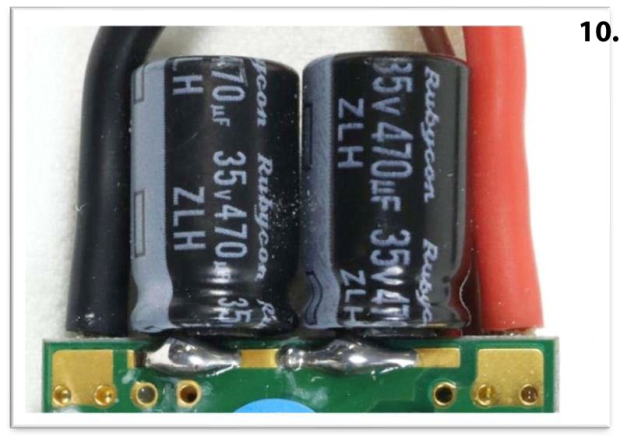
Every ESC has a large capacitor, or group of capacitors, right at the end of the PC board where the battery leads solder onto the ESC.
10. An example of this is shown in this photo.
The purpose of these capacitors is to store a charge of voltage at the end of the ESC, and then dump it into the ESC every time the FET transistors turn on and send a surge of current to the motor coils. By having a reserve supply of voltage right at the input to the ESC, you minimize the surge of current that needs to be supplied through the battery leads, and thereby reduce the voltage fluctuations to the ESC.
After the capacitors dump the stored energy into the ESC, they need to charge back up before the next motor phase turns on. When the wires between the battery and the ESC gets longer, you have a larger voltage drop across the leads, and the capacitors must work much harder to store the next charge of energy.
ESC’s can dump the energy stored in them very quickly, and if you are moving large amounts of energy into and out of the capacitors very quickly, this can cause them to heat up. Over the course of a flight, if you have really long leads between the battery and ESC, the capacitors can get so hot that it causes the liquid electrolyte inside them to boil. The pressure then builds up inside the capacitors and can get so high that the little aluminum cans that make up the outside of the capacitor burst from the pressure.
If you must use longer wires between the battery and ESC, there are 2 ways you can minimize the stress on the capacitors. The first way is to simply use an ESC that is much larger than you actually need. Larger ESC’s have larger size capacitors on them and will be able to handle the extra voltage ripple caused by longer battery leads without overheating and becoming damaged.
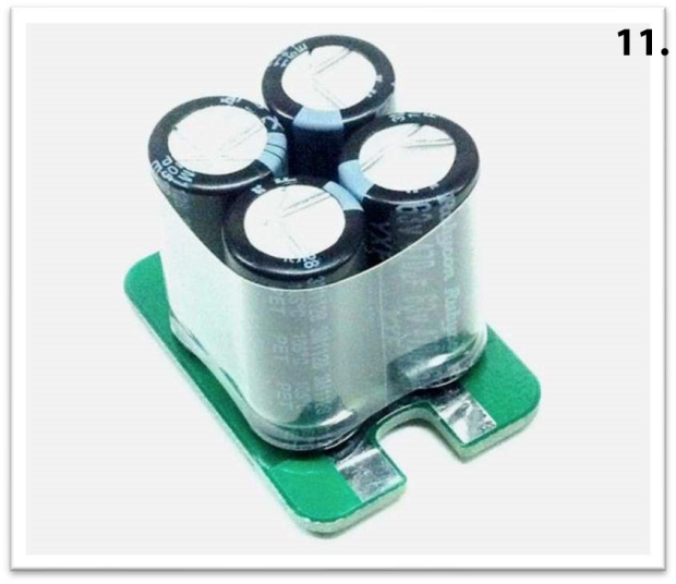
The second way is to add an auxiliary capacitor board to your ESC. Several companies make little PC boards, that have several capacitors soldered onto them, which are designed to be added to an ESC to provide the extra capacitance needed when using longer battery leads.
11. An example of this type of capacitor board is shown here.
These are installed by stripping a bit of insulation off the input leads to the ESC and soldering the board between the positive and negative lead, as close as possible to the ESC. When you extend the leads between the ESC and the motor, you really do not need to do anything, and the leads can be extended several feet, if necessary, with no ill effects. Multirotors do this all the time, with the ESC’s in the center body of the craft, and the 3 motor leads running a couple feet or more through the arm tubes and out to the motors at the end of the arms.
Running Undersized ESC’s at Partial Throttle
Another common misconception that a LOT of modelers have is running an ESC that is not large enough to handle the full current of the motor. They will rationalize this by saying, “I never run the ESC at more than ¾ throttle, so I will be OK” with the smaller ESC. Unfortunately, this is a recipe for disaster, which is caused by a misunderstanding of how ESC’s actually work.
Many people think that an ESC slows down a motor by reducing the voltage to it. This is simply not true. In its simplest form, an ESC is nothing more than a set of 6 electronic switches that rapidly turn on and off in a specific order to make the motor spin around. Whenever the ESC turns on power to a motor phase, all it can do is supply the full battery voltage to the stator coil. As we saw earlier in the section of how PWM works, the way that the ESC controls the speed of the motor is by varying how long the voltage is applied to the stator coils during each power pulse.
Every time that a FET turns on, you get the full throttle motor current for a brief period of time. For example, if you have a motor and prop combination that pulls 80 amps at full throttle, when you run the motor at 50% power, when the transistors are turned on the motor will pull 80 amps, and when they turn off you will pull 0 amps. If you put a wattmeter in series to measure the current, it will measure the average of these two values and show 40 amps of AVERAGE current.
If you have a 60-amp ESC on this motor, and “Never run it over 75% power”, on the surface it will look OK, because a wattmeter will show that you never pull more than 60 amps. However, what is actually happening is that you are pulling 80 amps 75% of the time and 0 amps 25% of the time. The tiny silicon junctions in the FET transistors are only able to handle a specific amount of current. If you pull more current than they are rated for they will start to heat up. If you were to look at the inside of the FET under a powerful microscope, you would see that there are small imperfections scattered around silicon junctions. In areas where the junction is a tiny bit thinner than others, you have a higher concentration of current, and this causes little hot spots to form. Over time, the continuous heating and cooling of these junctions weakens the material and can eventually cause stress cracks to form and cause a failure of the transistor.
This situation is similar to the “Paper Clip Effect”. If you take a paper clip and bend it 45 degrees and then straighten it back out, nothing really happens. You can repeat this process 20, 30, 50 or even 100 times and each time the paperclip straightens back out. Then suddenly on the next bend, when you go to straighten out the paper clip it snaps in half with no effort! What Happened?? It was perfectly fine the previous 100 bends, why did it fail now?
Every time you bent the paper clip the previous 100 times, the internal structure of the material was damaged at a microscopic level, invisible to the naked eye. At the atomic level, every time the paper clip was bent, the bonds were broken between a few atoms. Over time the damage accumulated to the point where eventually the entire part fails because of all the internal damage that has accumulated.
The exact same thing happens when you run an ESC that is too small for the motor it is driving. Every single flight it gets damage a tiny bit, on a molecular level inside the FET transistors. You might get 50, 60 or 70 flights with seemingly no issues, but then out of the blue, on the 71st flight the Esc blows up and you have no idea why. You will say, “I don’t know what happened, it worked perfectly fine for the last 70 flights!” Well, what was actually happening is the ESC got damaged a tiny bit each and every flight and eventually the damage added up to the point where the ESC suddenly failed.
To ensure the health of your ESC’s, and get the longest possible service life, the best thing to do is to observe the “80% rule”. If you run most electronic devices at 80% of their rated power, they will essentially last forever. This means that if you have a 40-amp ESC, you should never run more than 32 amps through it (40 x 0.8 = 32). Likewise, an 80-amp ESC should not be run over 64 amps and a 100-amp ESC should be limited to 80 amps of current. In most cases, the cost differential to go with an ESC that is 1 size bigger than the max current of the motor is typically only $10 or $15, and that is VERY cheap insurance to ensure that you ESC never has to work too hard and gets damaged. This is the most important thing that you can do to ensure reliability of your electric power system.
Can you run 2 motors from 1 ESC for a twin engine aircraft?
This is a common question that people ask quite often. Many will think that if you have 2 motors that pull 40 amps each, you can run both of them at the same time from a single 80 amp ESC. Unfortunately, it does not work that way. Because the ESC needs to sense the rotational position of the motor from the feedback it gets from the unpowered phase during each power pulse, if you have 2 motors running on the same ESC, and they are not EXACTLY in sync with one another, you get 2 sets of feedback pulses from the motors back to the ESC. These mixed signals can confuse the ESC and cause it to misfire. Also, if one motor starts up properly during the “Start-up” part of the ESC cycle, but the other one does not, you end up getting power pulses going to a motor that is not rotating, and the current will skyrocket out of control and burn up the speed controller.
Whenever you have multiple motors in an aircraft, each motor must have its own ESC to operate properly. While we are on the subject of multi-engine aircraft, this leads to another common question.
If I do run 2 ESC’s at the same time in an airplane, will both BEC’s work together and give me double the power available to run my servos?
Ideally, you should not connect the BEC circuits from 2 ESC’s together in parallel. This is especially true if the ESC’s have Switching BEC’s in them. The control circuit in a switching BEC is a closed-loop system that adjusts itself as the servo load changes to maintain a constant voltage. When the servos move under load they pull more current and this increase in current tends to pull the voltage output of the BEC down a little bit. When this happens, the BEC control circuit senses the change and automatically increases the width of the On-Time of the transistor to provide more voltage to the filter circuit. Adjusting 150,000 times per second, the BEC quickly adapts to the changing current and keep the voltage at a constant level. When the servo goes back to neutral and the load goes away, just as quickly the BEC circuit senses this and reduces the power going to the filter circuit once again to keep the voltage from being too high.
If you have 2 BEC circuits connected together, and one is putting out a tiny bit more voltage than the other, and the lower voltage BEC drops its output voltage a bit, the feedback circuitry does not see this and instead, reads the voltage of the other BEC. When this happens one of the BEC circuits loses its ability to regulate itself and cannot operate properly. For this reason, when you run 2 ESC’s together in a twin engine aircraft, and you use a Y-harness to plug both ESC’s into the same throttle channel, it is best to “Disable” one of the BEC circuits by pulling the red wire and its contact out of the control lead on that ESC, then fold it back and cover it with a piece of heat shrink or a piece of electrical tape.
In a twin engine aircraft, you can also accomplish this by cutting the red wire on one leg of the Y-Harness, where the ESC plugs into it, to prevent the BEC output from mixing with the other ESC. By doing it this way, you do not have to modify the ESC itself, and the cut wire in the Y-harness effectively makes it into a “Twin Engine Throttle Y-Harness” that automatically disables the BEC in the ESC that is plugged into the side with the cut wire.
Do ESC’s really need cooling air over them?
All electronics will generate some heat when they are run. How much they heat up depends on how hard they are pushed during operation. If you run a 100-Amp ESC with a motor and prop that pulls 98 amps, the ESC is going to get quite hot. If you run the same 100-Amp ESC on a motor that only pulls 52 amps, then it is probably only going to get lukewarm. When an ESC is mounted inside a fuselage, it is best if you cut or drill a few holes in the firewall, in line with the location of the ESC, so that come air comes in through the fuselage and carries the heat off the ESC and out of the fuselage.
Of course, if you want the heat to get out of the fuselage, there also has to be an air exit hole somewhere in the back part of the fuselage. A lot of aircraft that are designed for electric power will have a hole in the bottom of the fuselage, behind the trailing edge of the wing, to provide a way for the air that comes in through the firewall to escape. The air that comes in and goes past the speed controller also has a chance to go by the battery and carry some of the heat away from the battery as well.
When I power up my motor, it just quivers back and forth and will not spin. What causes that?
Whenever you have a motor that just quivers back and forth when power is applied, it means that you are only getting power on 2 of the 3 motor leads. When this happens, during each 3-phase power cycle, the motor will rotate forward 1 magnet width, then sit still for a second and then rotate backwards 1 magnet width and repeat this process over and over. When a motor is run this way, to the ESC it looks like a short-circuit, and HUGE levels of current will flow through the ESC and motor. If run in this condition for more than a couple seconds, the motor and/or the ESC will get hot very quickly and most likely fail in a large cloud of smoke.
The #1 cause of this kind of problem is a bullet connector on the motor that has residual solder flux built up in between the ring of spring contacts and the center post of the connector. Occasionally, when a bullet connector is soldered onto a motor lead, some of the solder flux will drip out of the vent hole in the side of the solder cup on the back side of the bullet connector and gets down in between the spring ring and the center post. When this cools back off, it re-hardens and the bullet connector acts like it has a coat of clear nail polish on it, which prevents a solid electrical connection.
Normally, any residual flux is washed out of the bullet connectors at the factory when the motors are built, but occasionally, one will have an excessive amount of flux inside that does not get washed out in the cleaning process, and this leads to an intermittent connection down the road. If the end user of the motor changes the bullet connectors on a motor, and uses too much flux, the same kind of situation can exist.
Fortunately, this situation is easy to look for and easy to fix. Whenever you get a new motor, you should always try to spin the ring of spring contacts on the bullet connectors if the bullet connectors have them. The spring contacts on clean connectors will spin very easily if you twist them with your fingers. If the spring contact feels sticky or gummy, or worse yet, will not spin at all, then it is certainly contaminated with solder flux and must be cleaned before the motor is put into service.
The best way to do this is with a small epoxy cup that contains some denatured alcohol. You can dip the connectors into the alcohol and spin them with your fingers until they spin freely. Sometimes it can take dipping the connectors multiple times to wash off all the flux. After they are clean you can wipe them with a paper towel or small rag, or blow them out with an air compressor or an air duster can to get all the alcohol out of the connector. Once the connectors are clean, the motor should perform well.
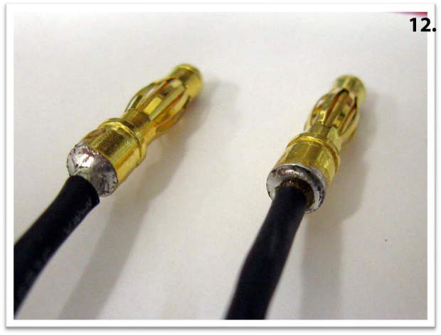
Another cause for this kind of issue is a cold solder joint on a bullet connector. When a solder joint is done properly, you will see a nice shiny fillet of solder running up from the connector into the wire. If you have a cold solder joint, the solder will suck down around the wire, and there will usually be a ring of crud around the wire where it enters the solder. The following photo shows a good solder joint on a bullet connector on the left, next to a cold solder joint on the right.
12. Here you can see the nice shiny fillet of solder wicking up the wire on the left bullet connector, and a ring of black crud around the wire on the right connector.
Many years ago, governments around the world enacted ROHS laws, which stands for Removal Of Harmful Substances. One of the things that was affected was solder. For decades, the solder that was used to make electrical connections was typically a mixture or 60% Tin and 40% Lead or 63% Tin and 37% Lead. Since Lead was one of the heavy metal contaminants that was banned as part of the ROHS Act, the alloy of solder had to change. Any solder that is used to assemble consumer electronics has to be Lead-Free now, and most of the solders used now are between 97 and 98% Tin, with the remaining percentage made up of various other metals such as Silver, Copper and Antimony.
These solders do work well; however, they melt at a higher temperature than the traditional Tin-Lead solder alloys melt at. This can create problems when modelers solder connectors onto ESC leads using the older Tin-Lead alloy solder, when the ESC leads were pre-tinned at the factory with the new Lead-Free solders. If you put a pre-tinned wire into the cup of a bullet connector, and then heat up the connector until solder melts and fills in around the cup, you can fill the cup without melting the solder in the wire. In cases like this, the joint seems good, because the wire is firmly held in place by the solder the user applied, but since the two solders did not flow into one another there is no solid electrical connection.
A solder joint like this may run fine for a while, but after several flights, the solder joint can work loose due to vibration, and the wire can at best, lose contact with the bullet connector, and at worst, fall right out of the connector! If this happens during a flight, the motor immediately goes into a locked rotor state, and massive amounts of current start flowing which very quickly burns up the motor and ESC.
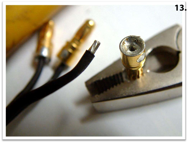
13. This photo shows a bullet connector that fell off a motor lead because the solder was not heated enough when the bullet connector was installed. If you look closely at the wire, you can see that the original solder on the motor leads never melted when the bullet connector was installed. This left a cold solder joint that failed a few flights later after the wire experienced a bit of vibration.
To prevent this from happening, it is best to re-tin the leads on an ESC with the solder that you are going to use to make the solder connections on the bullet connectors. By mixing some of this solder in with what is already on the wire, it lowers the overall melting temperature of the solder and greatly lessens the chance of getting a cold solder joint.
The other thing to ensure that you get good solder joints is to use a soldering iron that is large enough to do the job. A little 30-watt pencil tip soldering iron that you would use on a PC board will NOT get hot enough to properly solder connectors. You really need to have a temperature-controlled iron with a minimum of 60 watts of power to be able to get the connectors hot enough, quickly enough to do a good job. As a rule of thumb, if the iron you are using takes more than 5 seconds to get the connector and wire hot enough to solder, then it is not large enough to do the job. Ideally you should be able to heat the part up, apply the solder, and pull the iron away in about 3 seconds.
When I power up my ESC it will not arm. It just continuously beeps at me, what is wrong?
ESC’s operate from the same pulse width signal that is used to drive servos. Ideally, ESC’s need to have a signal with a pulse width of 1000uS at idle to arm properly, and a pulse width of 2000uS at full throttle to be able to reach 100% throttle. Many modern digital radios have channels that only put out signals in a range from about 1080uS to 1920uS. This is fine for a servo, which instead of rotating +/- 45 degrees from center will only move +/- 42 degrees from center. However, for most ESC’s to properly arm, the pulse width at idle must be below 1040uS.
If you have a Servo Pulse Meter (Which every modeler that flies Electric powered models SHOULD have!) you can plug it into the throttle channel of your receiver and see the pulse values that you are getting at idle and full throttle. If you are seeing something like a range of 1080uS to 1920uS, you can go into your servo travel volume or servo endpoint adjustment menu in your transmitter and change the endpoints from 100% at each end to something like 108% or 110% or whatever it takes to get the throttle to go from 1000uS at idle to 2000uS at full throttle. You also want to make sure that your throttle trim level is centered, because this can also throw off the endpoints of the throttle channel.
Another thing to remember is that if you are flying with a Futaba transmitter, that brand has the throttle channel backwards compared to other brands of radios. The default on Futaba radios is 2000uS at idle and 1000uS at full throttle. For these radios to work properly with ANY speed controller you MUST reverse the throttle channel in the transmitter servo reversing menu.
Many ESC’s also require that a Throttle Endpoint Calibration be run on the ESC the first time you hook it to a transmitter and receiver. For most ESC’s the way to do this is to turn on the transmitter with the throttle wide open. Then power up the speed controller with a motor attached, and immediately after you hear the first beep tone come from the motor you quickly close the throttle to idle. This allows the ESC to store the pulse width values for high throttle and low throttle in its memory, and then it can scale the entire throttle range properly, so it works well over the entire throttle range.
A combination of getting the transmitter to send out the proper range of throttle signals and performing the Throttle Endpoint Calibration will normally get an ESC working properly if it is not arming.
Wrapping Things Up
As you can see, the Speed Controllers used in our model aircraft are quite complex, with a lot of things going on “Under the Hood”. Hopefully, the information contained in this article has provided a better understanding of how these amazing electronic circuits actually work, and answered some of the most common questions and misconceptions that modelers have about them.
With the knowledge gained from this information, you should be able to make a more informed purchasing decision the next time you need a Speed Controller for one of your model aircraft.
Lucien Miller, president, Innov8tive Designs, designs motor systems for both hobby and professional markets, to learn more, please visit www.Innov8tivedesigns.com.