Building a Robotic Bird
by Nathan Chronister
You’ve probably seen some of the mechanical birds, called ornithopters, that have been devised recently. It’s amazing to watch a mechanical device power its way through the air with flapping wings. But most of these ornithopters are not what we could call a true “robotic bird”. They fly around with simple radio control, just like any radio-controlled airplane. They don’t have the on-board intelligence that we incorporate into our ground-based robots. That’s all about to change, as the latest generation of flapping-wing models takes on a much smarter design.
The first innovation is the use of servos to power the wings. This may not sound revolutionary to anyone involved with building his or her own robots. However, it has only been in the last few years that we could get servos powerful enough to serve as the motive power for flapping-wing flight. Up until recently, we had to use a motor and gear drive to get enough power. That never allowed much control over the movement and positioning of the wings. Now, with servos to flap the wings, we can totally control the wing movements. This opens up a world of new possibilities, not the least of which is that it now becomes much easier for you to build an ornithopter of your very own.
The second innovation is the use of a microcontroller, to coordinate the wing movements of the recently introduced servos. These two ideas fit together nicely, to give us the first truly robotic flying birds. Once we have the microcontroller on board, we can start to program the robotic bird with any desired behavior. We can add gyroscopic stabilization, sensors, GPS, or other features that are found in robotic vehicles.
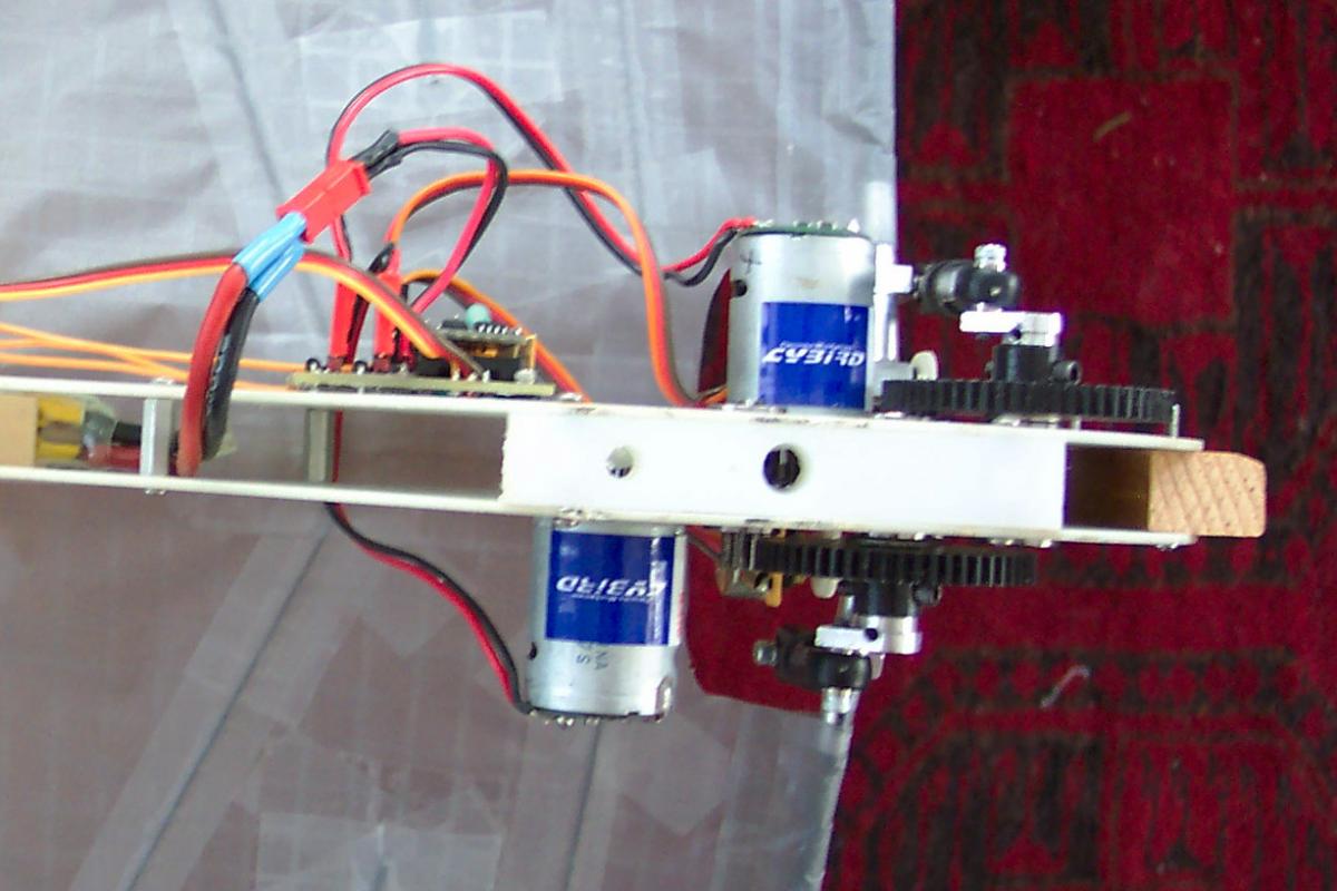
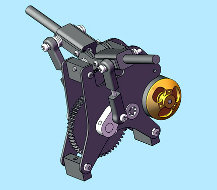
I built my first “robotic” ornithopter in 2005. Called the “Raven” due to its onboard intelligence, it had separate motors driving the left and right wings. Each motor and gearbox was constructed in the conventional way, but I incorporated a potentiometer into each wing hinge, to sense the position of the wing. This information went to a BasicX-24 microcontroller, which could vary the amount of power to the two motors. The positional feedback system amounted to a custom-built servo, and it offered some of the benefits that would be expected from a servo-powered ornithopter: The two wings could be controlled independently, for a wide range of different flight maneuvers. The wings provided all flight control functions, instead of having to provide an additional mechanism in the tail for steering. The wings could be stopped at a favorable position for gliding when the power is off. Unlike the hobby servos available at the time, the dual motor drive system provided an enormous amount of power. However, the Raven was very elaborate to build.
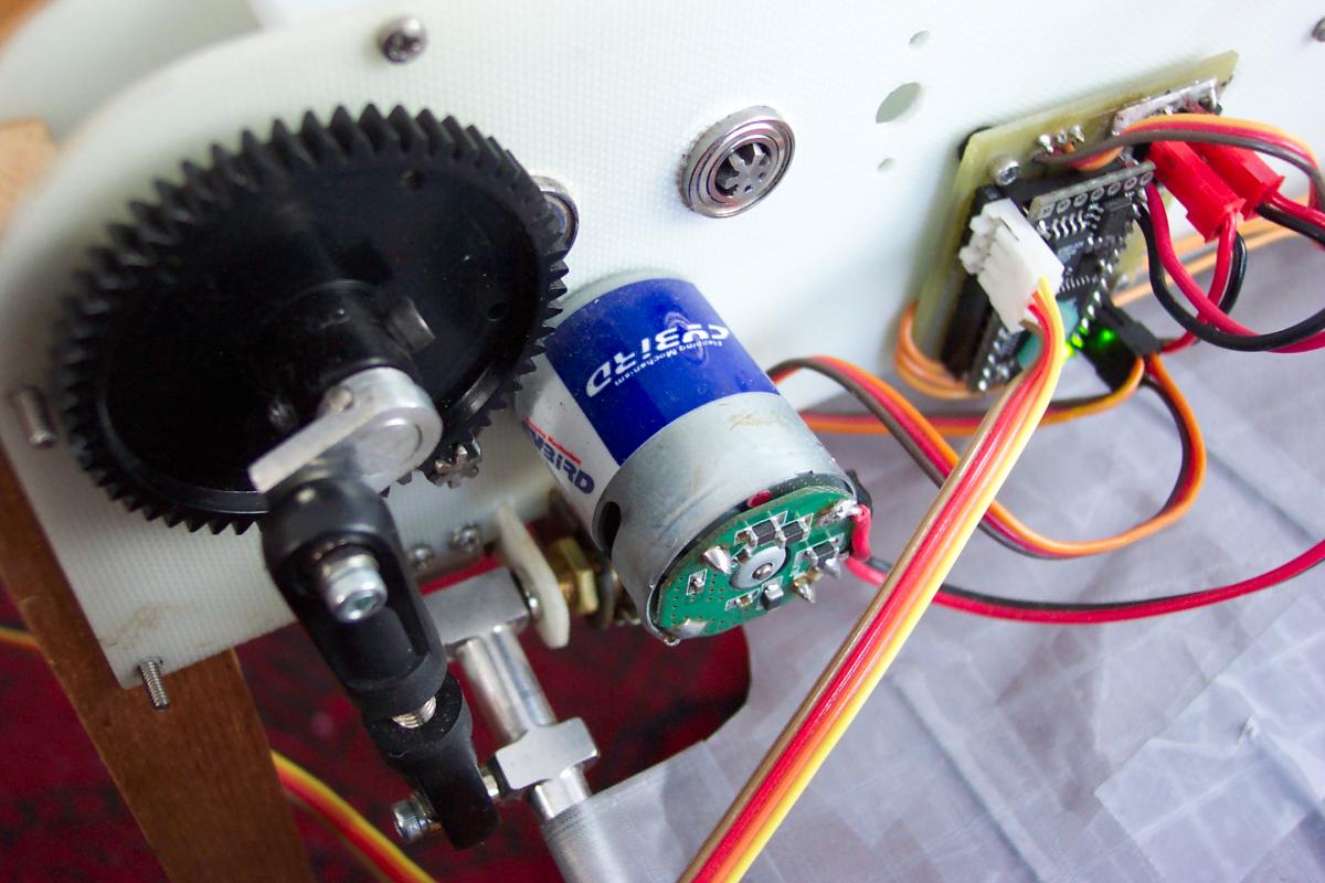
Nathan Chronister’s 2005 “Raven” RC ornithopter had custom-built “servos” that provided enough power for flight and allowed independent control of the two wings.
Soon after that, I learned that Hitec had introduced a new type of servo. Their digital robot servo, HSR-5990TG, had some advanced features that I thought might make it suitable for driving an ornithopter. First, this new servo had a titanium gear train that would stand up to a lot of abuse. Second, it used a better type of transistor, called MOSFETs. They have very little resistance in the “on” state, and that means very little energy wasted as heat. This would allow more efficient operation and a higher power output. The new servos were also designed to operate at a higher voltage, and they could produce far more power, for their weight, than any previous hobby servo. It remained to be seen if this would be enough power for flight. Hitec was kind enough to donate a pair of the digital robot servos, to facilitate the development of a prototype.
New Category of Flying Robot
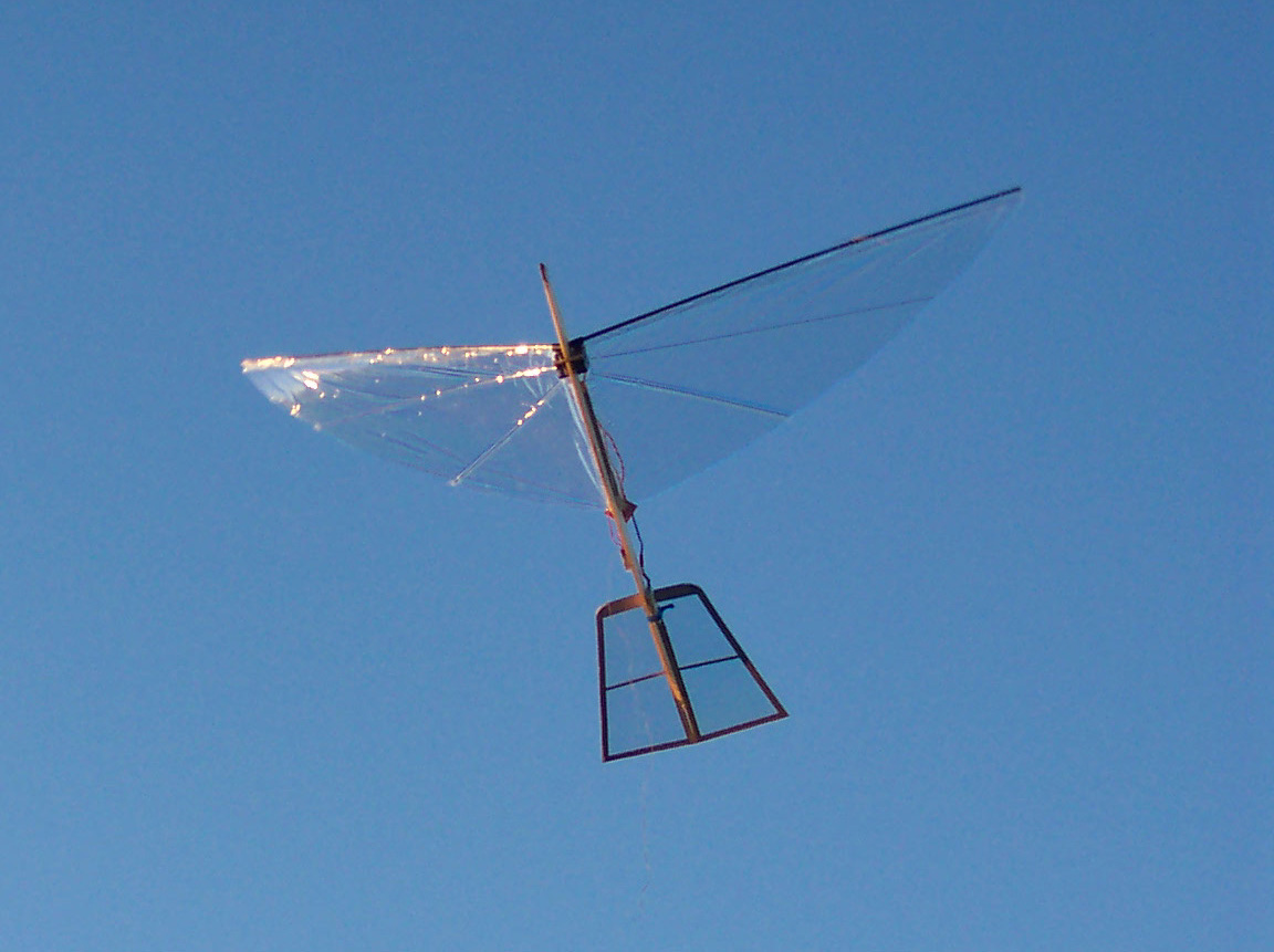
The S-1 Robotic Bird began its first test flight with a very simple microcontroller program, and no radio control. Not sure what to expect, I programmed it to flap the wings only five times and then go into a glide. I waited for a perfectly calm morning, drove to the flying field at the nearby elementary school, and stood there with the model in my hand, trying to mentally prepare myself to deliver a suitable hand launch without any way of knowing how the model was going to behave. I connected the power and positioned the giant bird for launch, while the programmed time delay elapsed. When the sleek robotic bird finally took off, it darted forward from my hand and accelerated across the field with startling vitality. After the planned five wing beats, it went into a graceful glide and landed gently in the grass. A whole new category of flying robot was born.
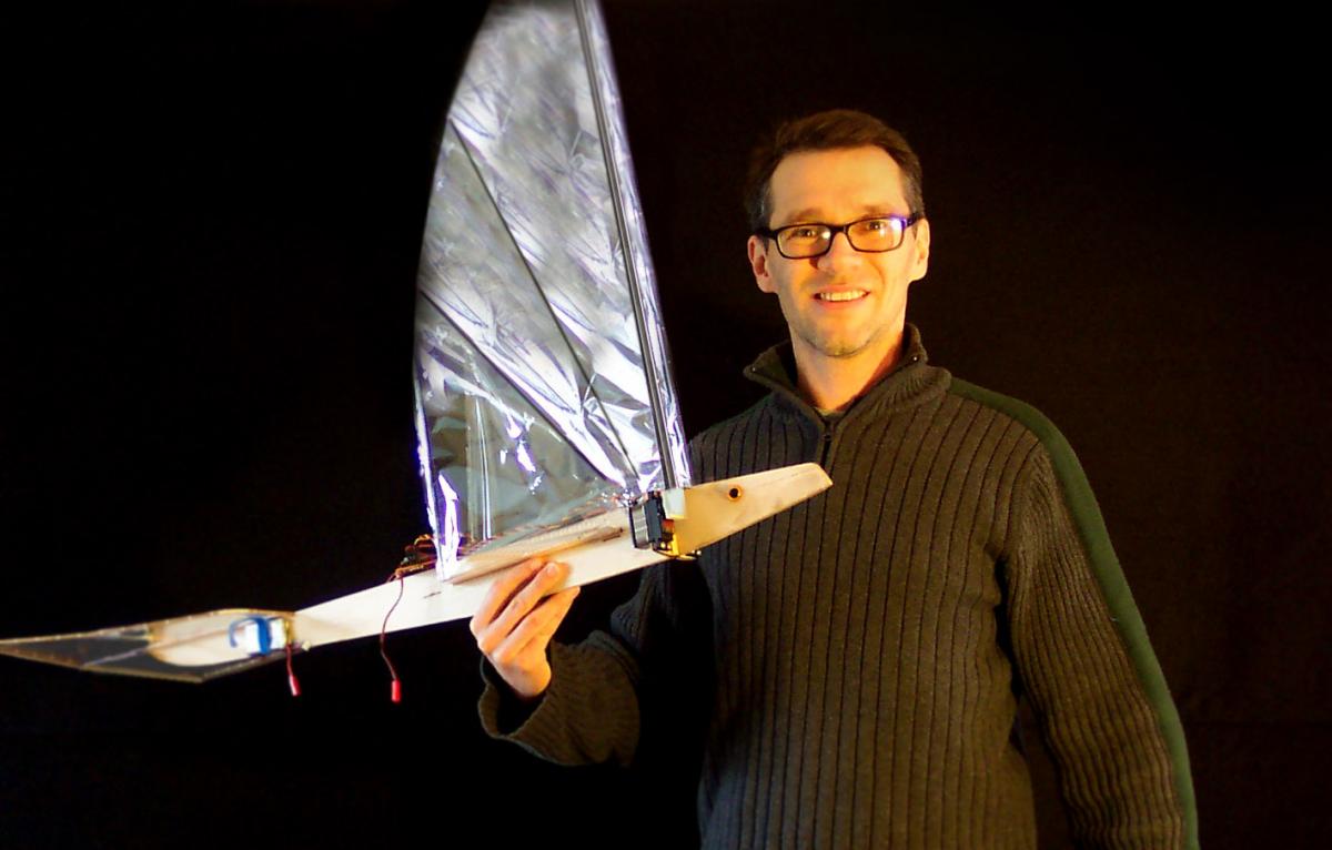 Here, the author is holding the S-1 Robotic Bird, which is a servo-powered “ornithopter” or flapping-wing aircraft.
Hitec later introduced a line of brushless digital servos, which are even better than the digital robot servo that I began with. The brushless digital servos come in three different flavors: high torque, multi-purpose, and high speed. The brushless motor makes them all a lot more efficient than previous servos. They also have a regenerative braking system, which recaptures momentum at the end of each wingstroke. It’s almost as if they had been designed specifically for flapping wings! Recently, some other manufacturers have started to sell their own servos that are powerful enough for flapping-wing flight. The Hitec servos are still the best.
Which Aervo to Use?
Hitec makes three different versions of their brushless digital servo. They all look the same, and they are all the same size and weight. How can we decide which servo to use for a particular ornithopter?
The difference between the three servos is hidden inside, and that difference is the gear ratio. The “ultra-torque” servo moves slower, but exerts a stronger force. The “high speed” servo is faster, but it doesn’t have as much torque. The “multi-purpose” servo is in the middle. The manufacturer has given us the torque and speed for each of the servos.
Recommended Torque, Speed & Wingspan for Hitec Brushless Servos

HSB-9380TH
ultra torque
Torque: 34.0 kg-cm
Speed: 0.14 sec/60°
Wingspan: 2.2 meter
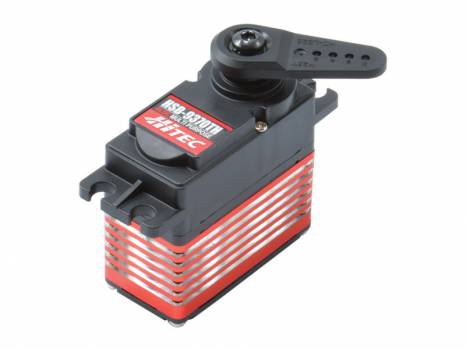
HSB-9370TH
multi-purpose
Torque: 25.0 kg-cm
Speed: 0.10 sec/60°
Wingspan: 1.7 meters
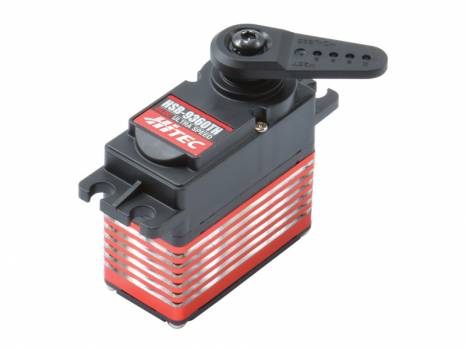
HSB-9360TH
high speed
Torque: 17.0 kg-cm
Speed: 0.06 sec/60°
Wingspan: 1.2 meters
To figure out which servo is best, for a particular ornithopter, I used a combination of theoretical analysis and empirical testing.
First, I flew the S-1 Robotic Bird with each of the three servos. With the “ultra torque” servo, the S-1 Robotic Bird could make a lazy climb, and it could maintain its altitude in a turn. However, I wanted to see how it would fly with a faster servo. As it turns out, even the “high speed” servo still had plenty of torque to flap the large wings. It could flap the wings more vigorously than either of the other servos, and the rate of climb was better than most conventional ornithopters. However, it was running with too much load. Instead of running efficiently, it was producing a lot of heat. Therefore I concluded that the “multi-purpose” servo would be the best choice for this particular model. It gave a good rate of climb and ran cool, drawing only two amps at full throttle.
The S-1 Robotic Bird is big and light weight. It has a 67 inch wingspan, yet it weighs only 10 ounces. As a first attempt at servo-powered ornithopters, the large wings would allow it to fly with the minimum amount of power, while also operating at the slow flapping rate that servos were expected to deliver. Experience suggests that this approach wasn’t necessary. We aren’t limited to this “slow floater” type of ornithopter. I decided to build a new, more compact ornithopter specifically for the “high speed” servo.
Using some basic aerodynamic theory, I derived a formula that should give the correct wingspan for any servo:
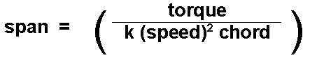
For this to work, the torque should be in kg-cm, and the speed should be in degrees per second. “Chord” refers to the width of the wing, and in this case it’s the widest point, where the wings meet the body of the ornithopter.
The constant k was determined from my experiments with the S-1 Robotic Bird. A certain similarity in the wing design is therefore assumed, but many years of experience have shown this to be the simplest and most consistently successful wing design for an ornithopter.
Using the formula, here is how we would calculate the correct wingspan for the “high speed” brushless digital servo:
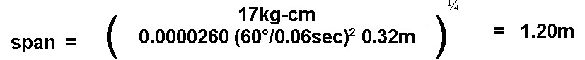
I built a new servo-powered ornithopter with the calculated 1.2 meter wingspan. Sure enough, when the model was built at this wingspan, it flew great. The smaller wings resulted in a much faster-flying bird. It still retained a good rate of climb. And the servos stayed cool. As an added benefit, the shorter body allowed me to give it a more realistic appearance than the current S-1 design.
The S-1 Robotic Bird is available as a kit from BirdKit.com, and the smaller, faster version will be on the market soon. A pre-programmed flight controller can be purchased, which will drive the wing flapping in the robotic bird. For those readers who are interested in programming their own robotic flight behaviors, I will provide an overview of how to program the wing movements yourself.
Basic Flapping
I’m going to assume that if you are reading this article, you already have some experience with robotics. You may already know how to program a microcontroller, and how the microcontroller can be used to control an RC servo. If that is not the case, I would recommend purchasing a starter set, such as the BASIC Stamp Activity Kit, available from Parallax, Inc.
The first step in programming your robotic bird is to establish an up and down motion of the wings. There are various ways to program this. The simplest method would be to establish a top and bottom wing position, and tell the servo to go back and forth between the two positions. It will take a certain amount of time for the servo to travel between those two points. For example, if the wings are flapping five times a second, each full cycle will take 200 ms and each stroke up or down will take about 100 ms. About the same time that the wings arrive at the upper position, you are telling them to go back to the lower position. If the wings are allowed to stop for any length of time in the upper or lower position, that will reduce the flight performance.
In times past, if you wanted to build your own ornithopter, you would need to build your own gearbox and flapping mechanism. This was a very difficult task, and it was often very frustrating. Now, we can simply bolt on two servos, and we’re ready to go.
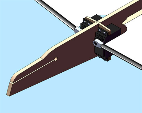
Clockwise vs. Counter-Clockwise Servo Rotation
Notice one thing about the servo-powered wings. The servo for the right wing is going clockwise to raise the wing. Meanwhile, the servo for the left wing is going counter-clockwise. For this reason, the actual pulse width that you send to the servo is going to be different for the two servos. If the neutral position is 1500 μs, then the top of the upstroke might be 1800 μs for the right wing, and 1200 μs for the left wing. At full power, you will want to flap the wings through an angle of about 60 degrees.
If you prefer, you can specify a new position of the wings, for each program cycle. For example, you might use a sine function to determine the correct wing position at a given point in time. However, I like to use a simple lookup table to generate the basic wing positions. This uses more lines of code, but it’s less processor-intensive. Once we have established the basic flapping motion, we can modify the wing positions to provide a variety of steering functions.
Steering Left and Right
Servo-powered ornithopters allow multiple steering methods, without any additional servos, without any mechanical linkage, and without any separate control surfaces. With only the two servos that flap the wings, you can have four or more independent control functions. You might enjoy the challenge of experimenting with various wing movements to see what kind of aerobatic maneuvers you can come up with. For basic steering, there are two methods that I have used.
The first method has the same effect as the rudder on an airplane. I will call it the “virtual rudder” method, because there is no actual rudder on the ornithopter. We raise one wing slightly, while lowering the other wing. The adjustment is superimposed on the regular flapping motion, so throughout its flapping up and down, the wing will be a little higher (or the other wing lower) at any point in the cycle. This is easy to program. You simply add a few microseconds to both of the outgoing servo pulses. Since the left and right servos are always rotating in opposite directions to each other, adding to both servos will cause one to go up while the other goes down. This steering method works in flapping or gliding flight.
For the second method, we change the timing of the two wings. For example, the right wing will reach the top of its travel, slightly before the left wing, and it will also finish its down stroke a little sooner. This causes the bird to roll to the left, having a similar effect as the ailerons on an RC plane. I program this using a lookup table, with a separate set of values depending on the amount of timing difference that you want. This “phase-shift” steering method is only applicable for flapping flight. While the bird is in its glide mode, we will use the virtual rudder steering method instead.
Steering Up and Down
We can raise or lower the flapping arc to make the bird go up or down. Raising the wings results in a higher line of thrust, which points the nose of the bird downward. Lowering the flapping arc gives you a lower line of thrust and pitches the bird up toward the sky. This works in flapping or gliding flight, and it has the same effect as the elevator control on an airplane. Since the left and right servos are normally running in opposite directions to flap the wings, we are going to add to one servo pulse while subtracting from the other.
Position the Wings for Gliding
For gliding, we set the wings at a certain position, which is usually about 15 degrees above horizontal. To this basic glide position, we add or subtract the appropriate rudder and elevator commands. One of the great things about servo-powered ornithopters, compared with the conventional motor drive, is that you can gradually reduce the flapping angle to get a smooth transition between flapping and gliding flight.
In my previous career, I developed a science curriculum and taught field ecology lessons through a regional nonprofit. I have also provided many workshops about flapping wing flight. From an educational standpoint, a school project to build and program a robotic bird will be a great way to challenge a group of high school or college students. It will be more challenging than a robotic vehicle that stays on the ground. At the same time, the capacity for flight will provide an extra dimension of excitement that will give students an incentive to rise to a higher level and succeed at this project. I hope this adds up to great learning for your students, and I would love to hear about the results.
Nathan Chronister
Links
Birdkit.com, www.birdkit.com, support@birdkit.com
Hitec USA, Inc., www.hitecrcd.com, (858) 748-6948
Hitec Robotics USA, Inc., www.hitecrobotics.com, (858) 748-6948
Parallax, www.parallax.com, (888) 512-1024